|
|
|
Application Notes
Creo Elements/Direct Modeling (V16), Module Advanced Design, Simplification
Subject:How to reduce the level of detail of a part or assembly ?
Imagine you have to provide a sensitive design to a subcontractor and therefore need to hide design details. The aim is then to reduce the complexity of the assembly and the level of detail of the parts geometry but not to perform non-reversible modifications on the original project.
CoCreate Modeling solves this request by offering the module Simplification (as part of "Advanced Design")
Task details:
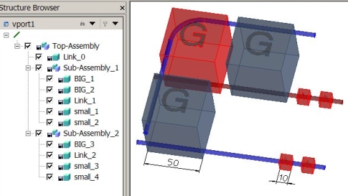
In the example below
- the red parts should be completely hidden from view
- the geometric "G" shaped features should also be removed
- Set up a Simplification (carrying all further definitions comparable to a study in FEA)
- Define rules to remove geometric features
- Specify on how certain faces should be handled
- keep a selection of faces
- remove a selection of faces
- Define rules on how to handle certain parts
- remove selected parts
- keep selected parts
- remove hidden parts, i.e. parts which are invisible from outside the assembly
- remove small parts
- Set up rules on how the system should act after
the initial simplification has been executed
- check the result for non-manufacturable parts
- check for validity
- simplify the initial simplification result again using the same rules, for example because the "merged" i.e. united result can show geometric situations which did not exist before and can be removed by further simplification.
- Further options to control the result and removed elements
.
and last but not least
. - Define whether or not the remaining parts should be "merged"/"united" and the original structure of the assembly will be hidden.
Note:
- All steps but the final execution are definitions or rule specifications.
- They are kept in the "Simplification" and saved with the owning assembly
- It is highly recommended to save the whole assembly (before and) after you set up the simplification but before you execute it.
- The definitions can be re-used if you made modifications on original parts or assemblies.
- Note: Once the simplification has been executed, the result is read-only ! If not saved before execution - at best to CoCreate Model Manager - the original status cannot be recovered (except using the UNDO button) !
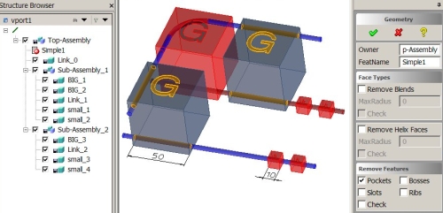
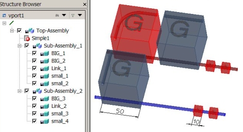
The following picture shows how to hide the "G" shaped geometric feature by removing "pockets". The system highlights all selected faces:
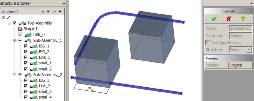
The image below shows an example on how to define which parts shall be hidden/removed:
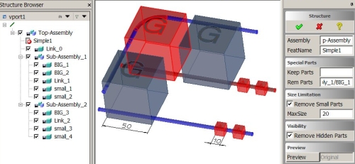
- "Rem Parts": A selection of parts: the red cube "BIG_1" and the red long "Link_1" should disappear
- "Remove Small Parts": Parts smaller than a given value: 20 mm
should not be visible any more. Later, the system will identify
"small_1" ... "small_4" to be smaller.
Note: The value approximately refers to the 3D diagonal of the parts box. Here, the edge length of the small cubes is 10 mm, the 3D diagonal is 17.3 mm.
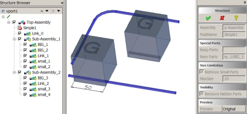
Preview shows how this definition will take effect:
- perform the geometric "Part Simplification" i.e. you can define the geometric simplification(s) but you do not have to execute them now.
- "Merge" the parts and assembly structure (uniting all remaining parts)
- leave the structure "Fixed" even though parts might not be visible any more. This is meant to show the original assembly structure but hide the geometric details.
Note:
In the sub-menu "Merge" you specify rules to take effect in case the
"Merge" option is used during execution. Here it's also possible to
define groups of parts which should not be "Merged"
(although the rest will be). These are called "Merge Groups" despite the
fact that they would rather act as "Non-Merge-Groups".
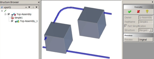
The "Preview" of the current definitions looks like:
At this point use the "Original" button! If you agree with the defined simplification, now is the time to save the original, non-simplified assembly including the defined simplification rules to the database !
Finally hit the "OK" button and check the simplification result:
Note:
The execution of a defined set of geometric simplification rules is an automatic process. For the sake of stability and getting a feasable, valid simplification result it may happen that some of the defined rules are not respected, because the result might become corrupt.
It is design intent and an expected behaviour that you might be able to manually remove geometric features which do not disappear in the automatically created simplified result although the defined rules could apply. Examples for such restrictions are: complex Blend-on-Blend situations, staggered features (bosses, pockets, slots) etc.
Note:
- The simplification result is "read only"
- If saved into CoCreate Model Manager, the simplified model is handled by a separate class and exists in parallel to the original, non simplified. If connected to the database, you can switch between the statii.
In the example above, all parts were connected in some way. (That's what the "Link_x" parts are used for).
In case not all parts are touching or overlapping and you apply the "Structure = Merged" option during execution, the "Unite" operation cannot create a single part only. Two or more parts have to remain:
The very same Simplification definitions now that the part "Link_0" has been deleted, provide in the following result:
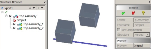
None of the original part names would be "correct" for a "merged" result. Therfore part names for the simplified part(s) are derived from the name of the assembly owning the simplification. Here: "Top-Assembly" owning the simplification set "Simple1" leads to the part name(s) "Top-Assembly_1" and "Top-Assembly_2"
It is currently not possible to define a structural rule removing certain parts and remove these (invisible parts) from the Structure browser only.
- If you select "Execute", "Structure Merged",
all parts will be merged/united and the whole
structure browser will collapse into "n" geometrically independent
parts.
. - If you select "Execute", "Structure Fixed", no parts will be united and the whole structure browser will remain in its original state.